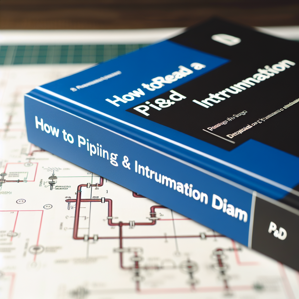
Understanding how to read a Piping & Instrumentation Diagram (P&ID) is essential for engineers, technicians, and plant operators involved in process design, construction, and maintenance. This guide will walk you through the fundamental steps to interpret these detailed diagrams effectively, enabling you to grasp the complexities of plant instrumentation and piping systems with confidence.
Deciphering the Symbols and Legends in a P&ID
One of the core aspects of reading a P&ID is understanding the standardized symbols and legends used throughout the diagram. These symbols represent a variety of equipment, piping components, valves, sensors, and control devices. Each symbol is designed to convey information efficiently and uniformly across the industry, but it can seem overwhelming at first glance. Here’s how to approach it:
- Symbols for Equipment: Look for icons representing pumps, tanks, compressors, heat exchangers, and other machinery. These are often standardized but can vary slightly depending on regional or company standards.
- Valves and Actuators: Recognize different types of valves – gate valves, globe valves, ball valves – often depicted with specific symbols, and note whether they are manual, automated, or actuated.
- Sensors and Instruments: Identify instruments such as pressure gauges, flow meters, temperature sensors, and control valves, typically marked with specific symbols indicating their function in the control system.
Familiarizing yourself with the legend key accompanying the P&ID is crucial. It provides the reference for all symbols used in the diagram, ensuring you can correctly interpret each component’s purpose and connection.
Following the Process Flow and Understanding Connections
Once you’re comfortable with the symbols, the next step is to follow the process flow logically. P&IDs are arranged to reflect the step-by-step flow of the process, starting from raw material input to final output. Here’s what to focus on:
- Understanding Line Types and Piping: Different line styles (solid, dashed, dotted) indicate various pipe types or states such as process flow, instrument lines, or pneumatic lines. Tracing these lines helps you understand how materials and signals move through the system.
- Identifying Control Loops: These are interlinked connections between sensors, controllers, and actuators. Recognizing control loops enables you to grasp how the system maintains process parameters like pressure and temperature.
- Locating Critical Components: Highlight key components such as safety valves, relief valves, and emergency shut-off mechanisms, which are vital for safe operations. Understanding their placement and connection ensures awareness of operational safety protocols.
Following the process flow in a logical manner not only aids in understanding the diagram but also assists in troubleshooting, maintenance, and optimization of processes within a plant or system.
In conclusion, reading a P&ID involves mastering the symbols provided, understanding the flow of materials and signals through lines, and recognizing key control systems within the plant architecture. By familiarizing yourself with these core elements and practicing on real diagrams, you’ll enhance your ability to interpret complex process diagrams confidently, contributing to safer and more efficient operations.