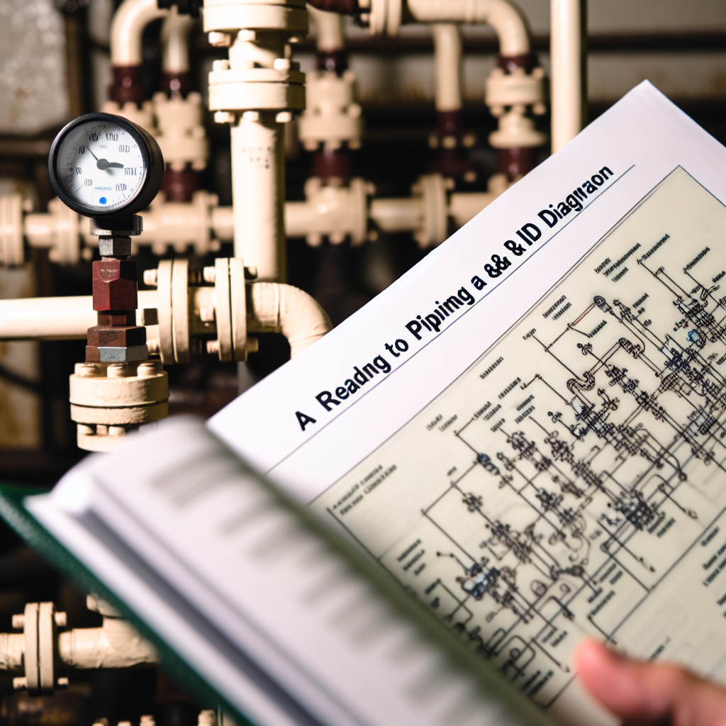
Understanding how to read a P&ID (Piping & Instrumentation Diagram) is essential for engineers, technicians, and plant personnel involved in process design, operation, and maintenance. This article offers a comprehensive guide to decoding P&IDs, highlighting key symbols and conventions to help you interpret these complex diagrams effectively.
Decoding the Symbols and Conventions on a P&ID
At the core of understanding a P&ID is familiarizing yourself with its symbols and standardized conventions. P&IDs utilize a set of symbols to represent various equipment, piping components, and instruments, often following international standards such as ISA S5.1. When reading a P&ID, start by identifying the legend or key, which explains the symbols used in the diagram.
Key elements to recognize include:
- Pipes: Usually represented by lines with different styles (solid, dashed, or double lines) indicating pipe types or functions such as process lines, instrument lines, or miscellaneous piping.
- Valves and Fittings: Symbols vary based on valve type—gate, globe, check valves—and fittings like elbows, tees, and reducers. Pay close attention to their labels and annotations for correct identification.
- Instrumentation: Include sensors, controllers, and indicating devices, often denoted with standard symbols augmented by tags indicating their type, range, and functions.
Mastering these symbols allows you to trace process flows, identify control points, and understand equipment placement in the overall system. Remember, a thorough review of the document legend is vital before analyzing complex sections of the diagram.
Following the Flow and Data in a P&ID
Once familiar with symbols, the next step is interpreting the flow of fluids and control signals within the diagram. P&IDs are organized to show the process flow from left to right or top to bottom, allowing you to follow material movement through piping, valves, and equipment.
Start at the process inlet and trace the flow path through various components, observing how control devices and instrumentation interact to regulate the process variables such as pressure, temperature, flow rate, and level. Pay attention to the sequence of operations, control loops, and safety interlocks embedded in the diagram.
Moreover, understanding the designation of instruments—such as transmitters, controllers, and final control elements—is crucial for troubleshooting and operational understanding. Color coding, tags, and annotations assist in linking symbols to real-world equipment and control schemes, thus enhancing your interpretation accuracy.
By following the logical flow and cross-referencing instrument tags with control loops, you develop a holistic view of the process. This knowledge is essential for effective operation, maintenance, and troubleshooting, making reading P&IDs a fundamental skill for process industry professionals.
In Conclusion
Mastering how to read a P&ID involves understanding standardized symbols, recognizing flow paths, and interpreting control and instrumentation details. Familiarity with these elements enables you to decode the diagram efficiently, facilitating safer and more effective plant operations. Developing this skill is vital for anyone involved in process engineering and plant management, ensuring clear communication and improved process understanding.
